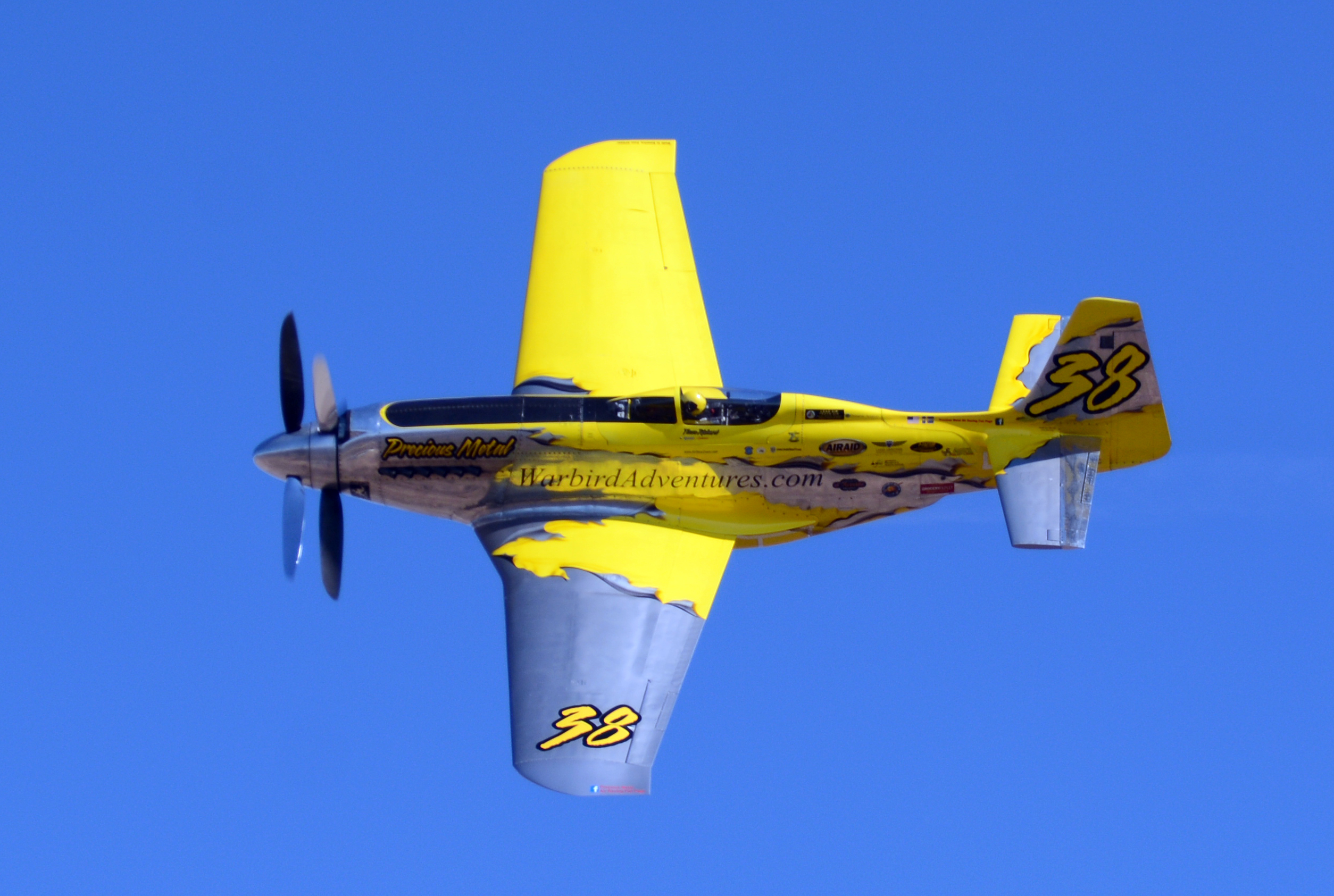
December 2019. Mert Bollman contacted myself to see If I would like to write a article on his Contra Rotating experiments, he supplied me with all the information and photos the following is my article, Mert also sent me a motor and I am presently looking for a suitable control line model to build about 33 inch wingspan, one which looks very interesting is the Martin Baker MB5, watch this space for information at a later date.
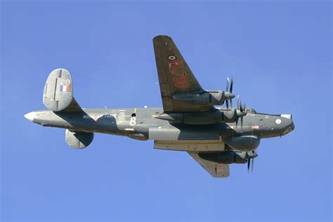
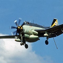
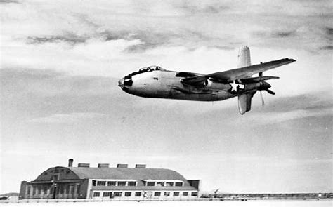
Contra-rotating propellers have a very long history dating back to the 1907 the original patent was taken out by F.W. Lanchester at this time, the main advantages of a pair of contra-rotating propellers are the torque on a aircraft is effectively cancelled out it has been found that these propellers are between 6% and 16% more efficient than a normal propeller, the main disadvantages are they can be very noisy and the weight of the gearbox drive units can be substantially high. Many aircraft have been made over the years with Contra-rotating propellers examples of these are, Avro Shackleton, Fairey Gannet, Spitfire MK XlX, Tupolev Tu-95 and the Douglas XB-42 Mixmaster to name a few.


Contra-rotating propellers fitted to electric motors have been around for some time in the model aircraft world however they are extremely expensive to purchase, their performance is very good but due to the high cost not seen very often, back in 2000 my fellow Modeller “Mert Bollman” from Spokane, WA USA decided to look for alternatives which could be used in all three disciplines Radio control, control line and free flight, also was it possible to manufacture a small lightweight complete assembly with motor and propellers at a reasonable price for which the average Aero Modeller could make without using any special tools or machines, this is where the story starts year 2000.

FAI F3A large model for Aerobatics Large motor about 60 IC equivalent.
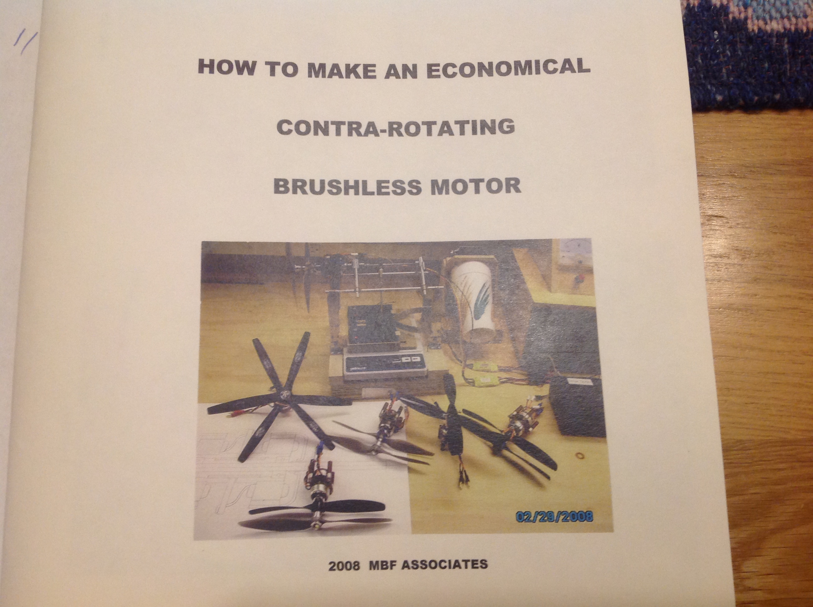
Mert’s first venture came with using Mubachi motors as they were the in thing for electric airplanes, the biggest problem he found was getting reverse rotation propellers at this time, a German company was selling a very nice propeller but not available in reverse rotation, also at about this time Brushless motors were becoming readily available from China making them easier to purchase instead of winding his own, the motors he purchased were able to turn larger propellers in both rotations but the completed assembly was larger than he expected, construction also needed access to a lathe and milling machine for certain parts, details are shown in his book “HOW TO MAKE AN ECONOMICAL CONTRA-ROTATING BRUSHLESS MOTOR” dated 2008, he continued to look for smaller brushless motors to suit his requirements.
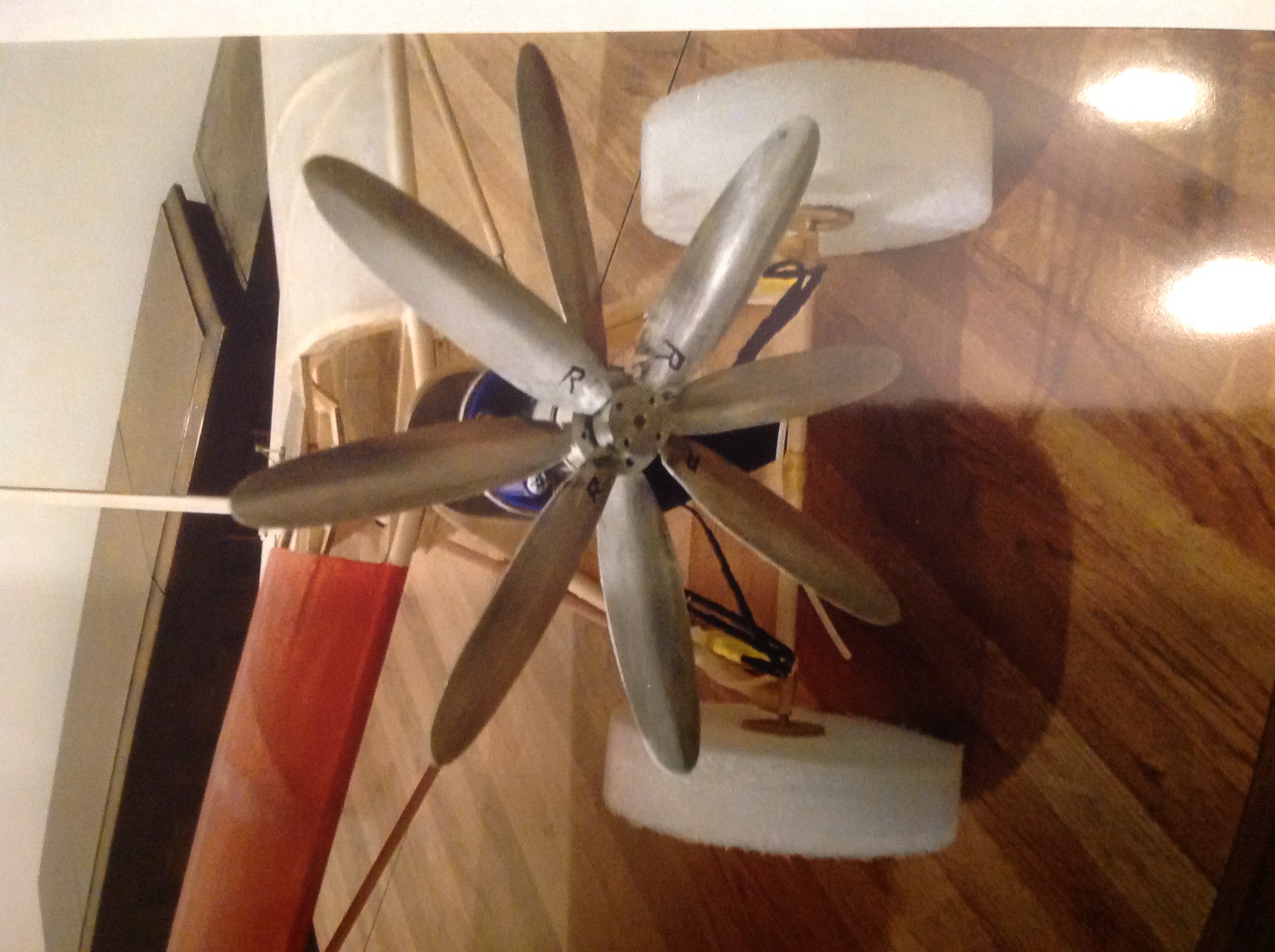
The main problem still was he had no propeller sets “Both rotations”, to try and solve this problem he decided to build his own plastic injection moulding machine, this operates at 400 F and plastic pellets for the propellers were made from cutting up paint pots, this made many different propeller shapes but all seemed to suffer from air bubbles in the finished product, laminating with a copper shim also did not solve the problem. The next step was to try making propellers from aluminium sheet this proved better but the airfoil shape was not perfect plus they are heavier, they also required a machined hub with a aluminium rod to help attach the blade to the hub, the complete assembly was welded together with a unique Russian design welder built in China, it was unusual as it uses a mixture of 50% alcohol and 50% water to generate the flame this produced a good joint without burning holes in the thin blades. Propeller pitch was set by using the rig shown in the photo.
Plastic injection machine
Range of plastic propellers
Propeller Jig
Metal Propeller
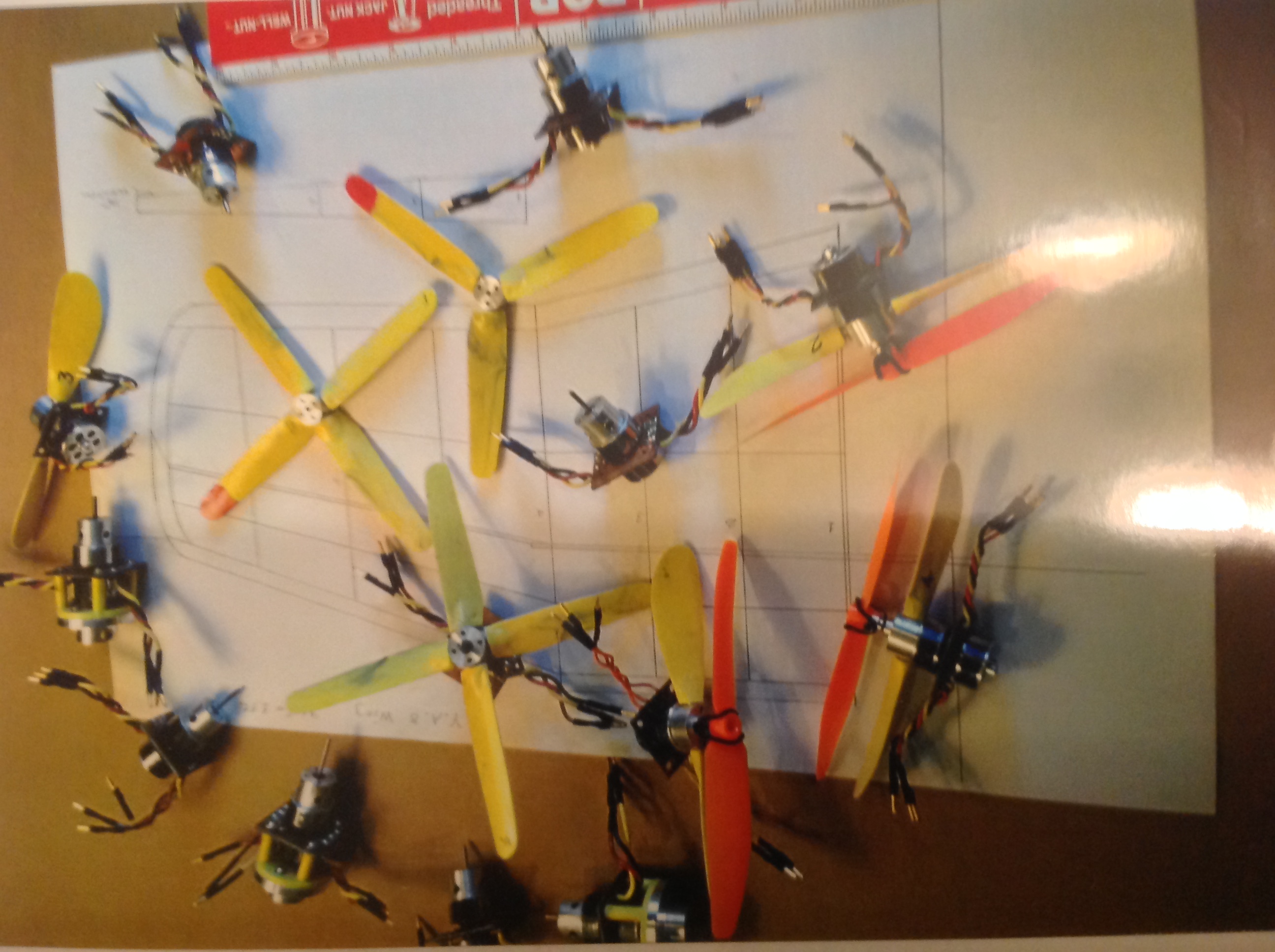
Moving onto motors, to save weight he tried to drive two propellers with one motor this would therefore only require one Electronic speed controller and the battery size could be reduced, the new gearing did not save much weight plus the complete assembly was very bulky however these did work. The next step was to try different centre drive shafts 2 and 3mm in diameter as ball races for this size were readily available, also at this time the RC drone came to the world market making a multitude of various inexpensive parts available including a very large range of propellers to suit his needs.
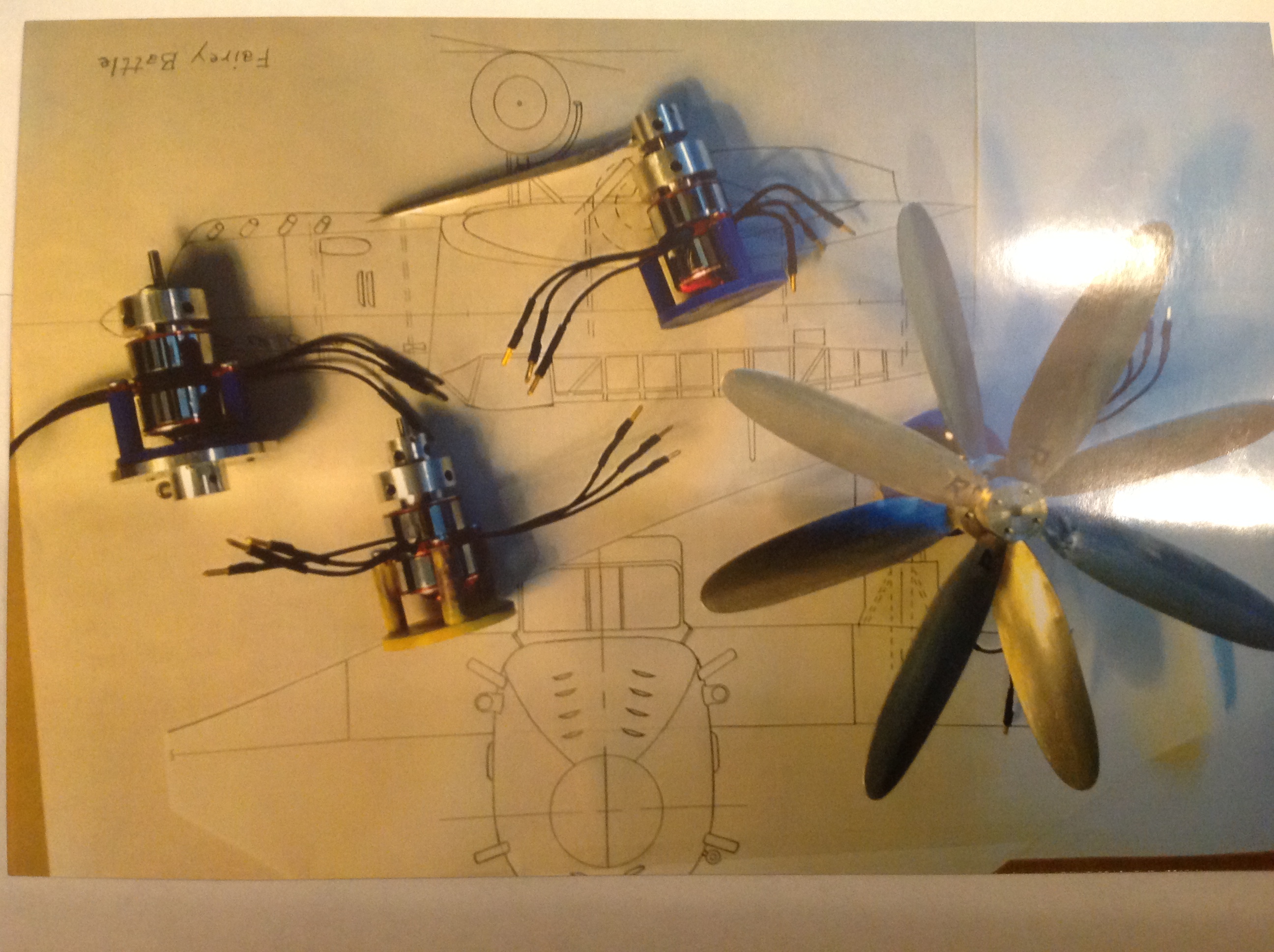
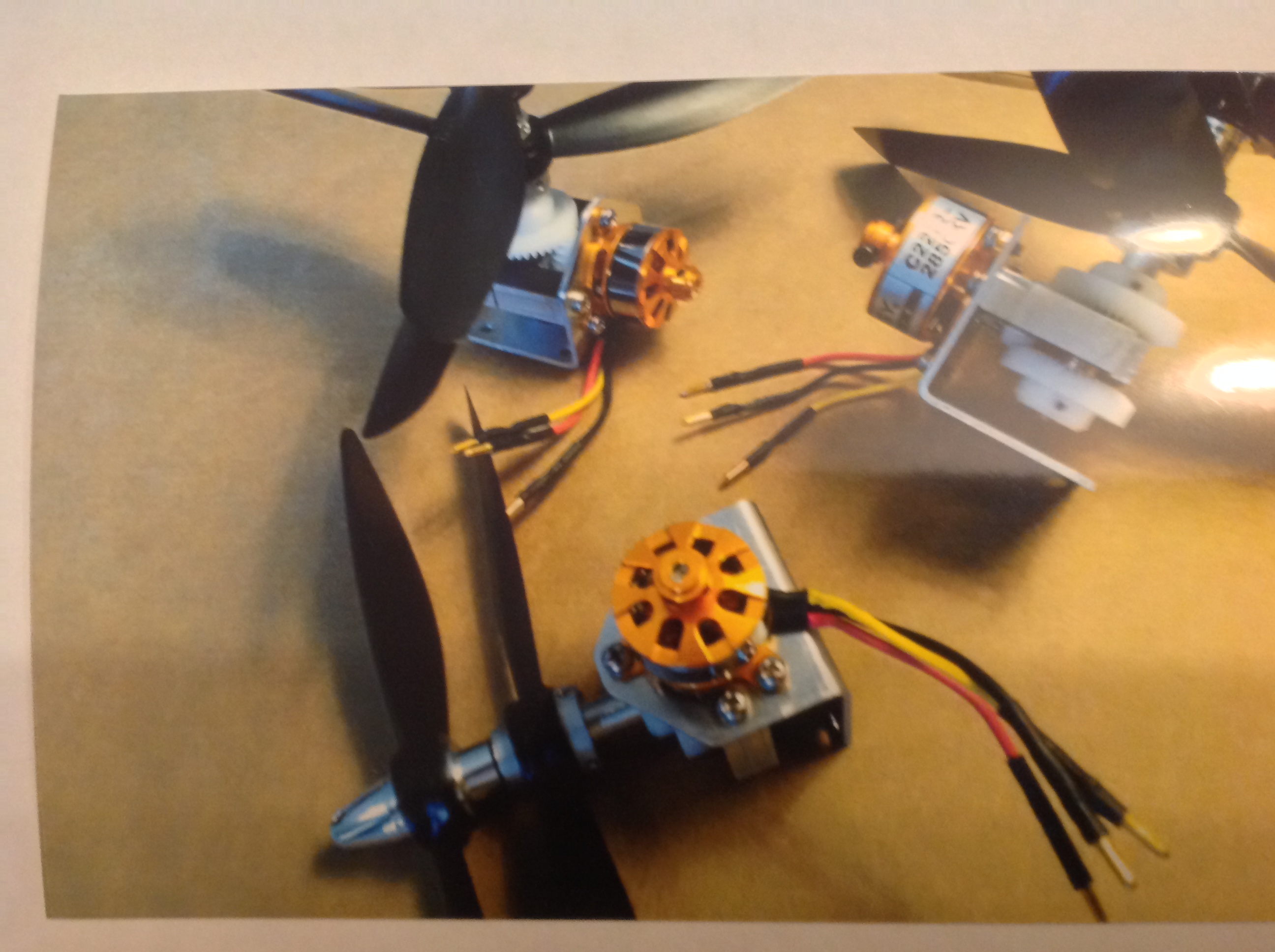
Metal propellers with motors
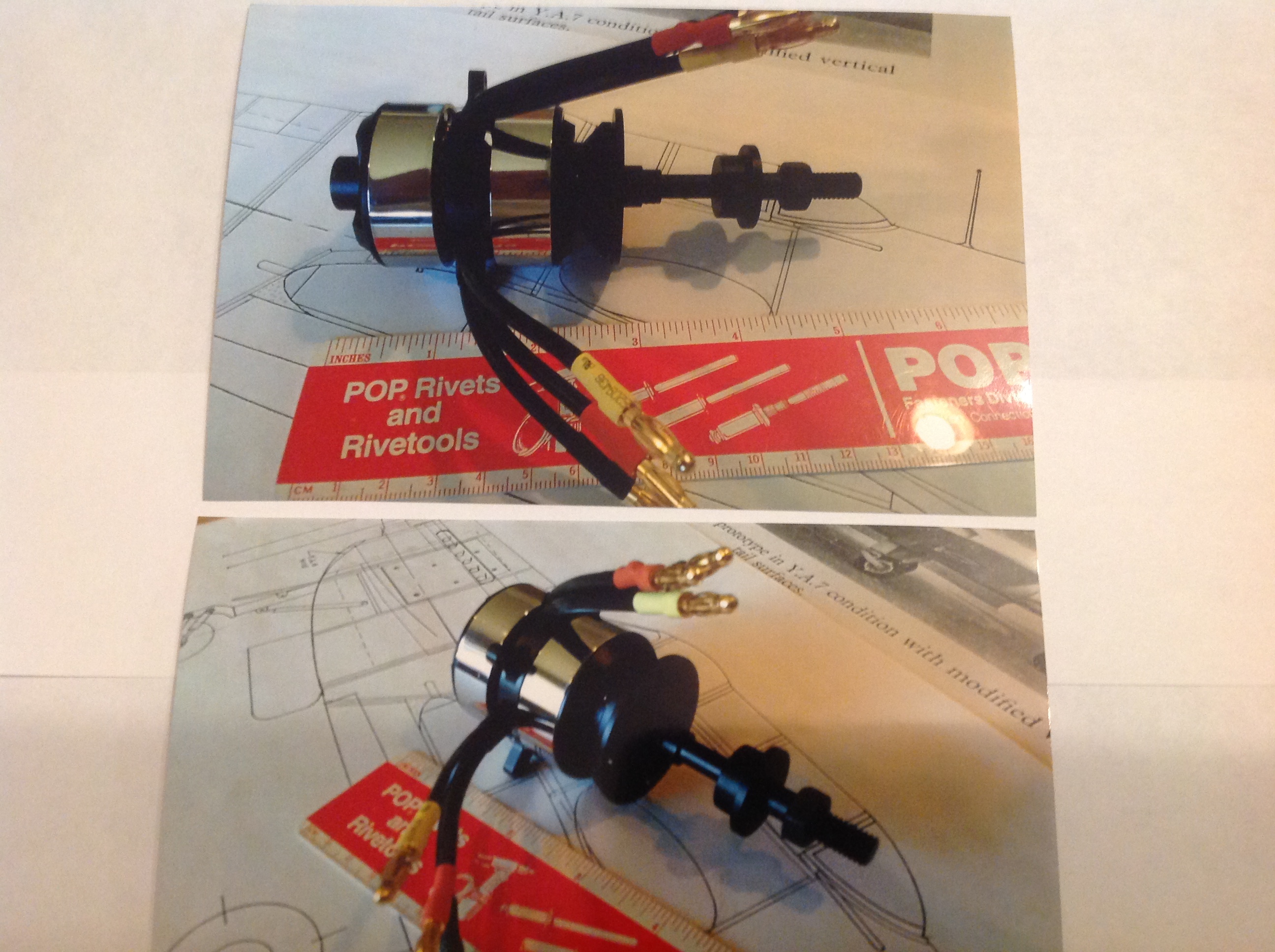
The first test model was a F4U Corsair this had a side motor mounting plate which has now been changed to a bulkhead type fixing, this motor has a extended shaft and the bearing are a tight fit into the housing this also helps reduce the vibration, this extended motor will now be fitted to the XB-42 model which is under construction now.
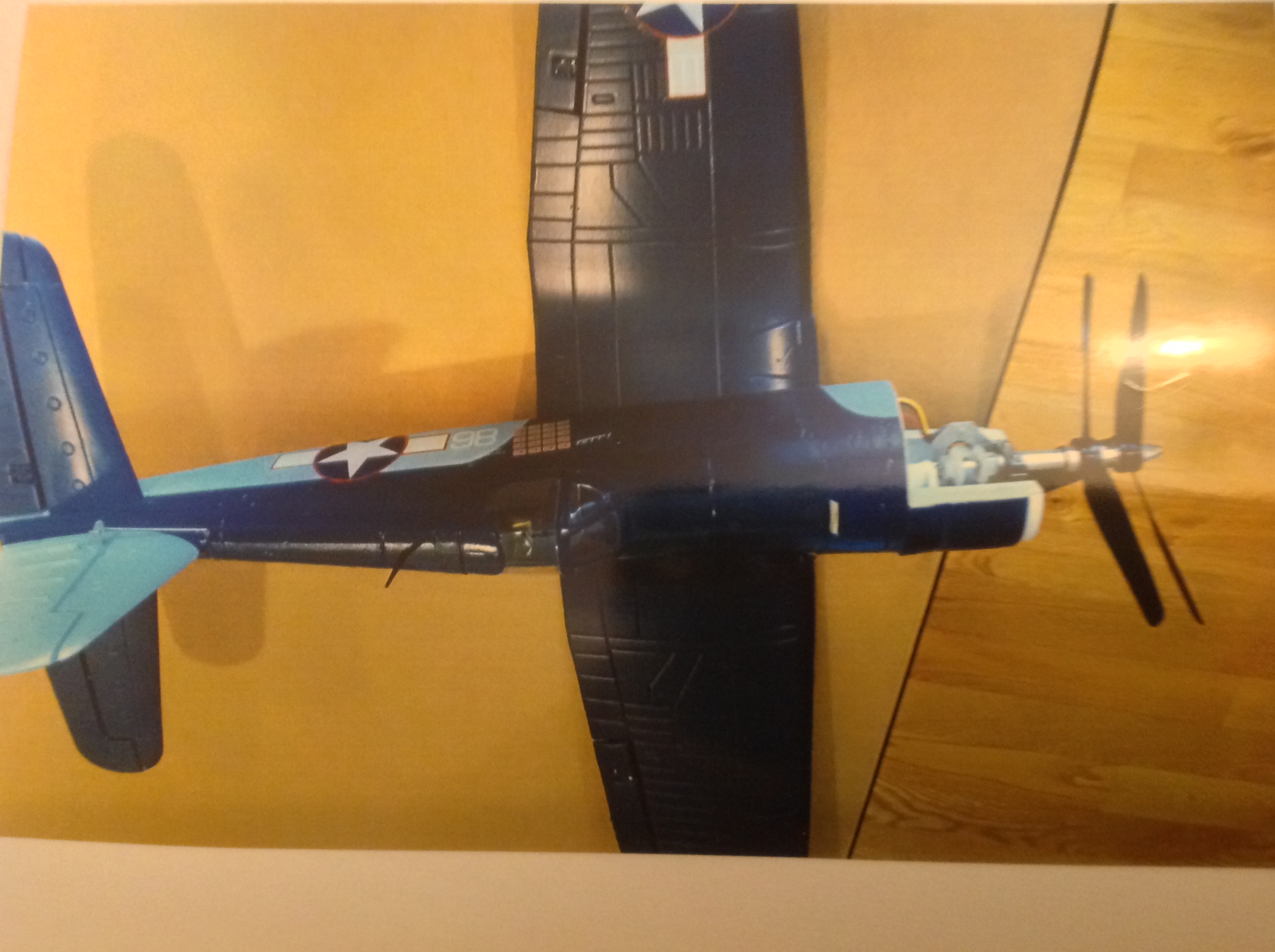
Corsair model

Long shaft fitted to XB 42
Now we come to the final version light weight and suitable for modellers to construct without any special tools or machines apart from a drill press see drawing concept 10, commercially available aluminium tubing is used in 3,4,5 and 6mm diameters supplied by K &S Precision Metals, aluminium sheet is used for the main bulkhead and 1/4 inch sheet for the main bearing support item ‘E’, metric ball-races are supplied from local hobby shops who deal in RC cars these fit the tubing sizes above, the nylon gear wheels are metric and are standard design and readily available without any problems however there could be a minimum order quantity, the motor is a Turnigy C 2222 rated at 2850Kv, propellers shown are Gem fan 8045 (8″ Dia 0.45 pitch) 2 blades or you could use a 3 blade propeller but reduce the Dia to 7 inch, motor any spinner came from HobbyKing, propellers were sought from China via E Bay. Mert has supplied me with large amounts of information and drawings including specifications fits and tolerances, I will now start with a brief outline of how the new motor assembly has been constructed full details can be provided by contacting Mert or myself see E mail addresses at the end.

Concept 10
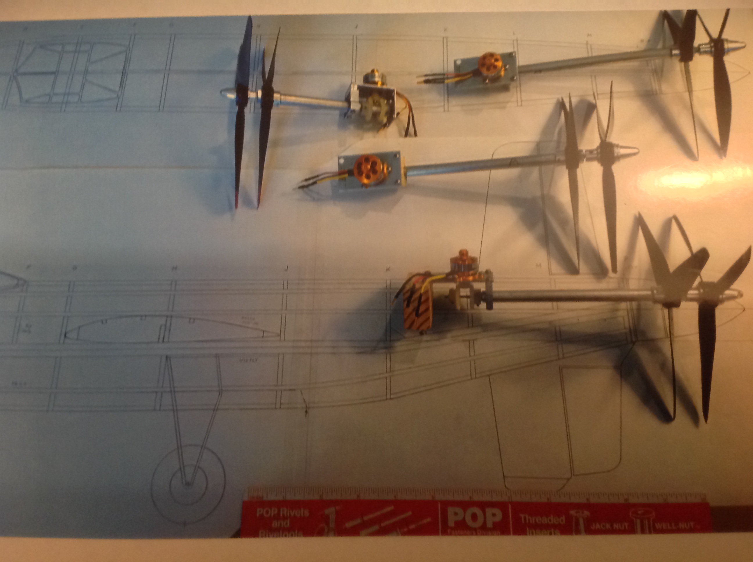

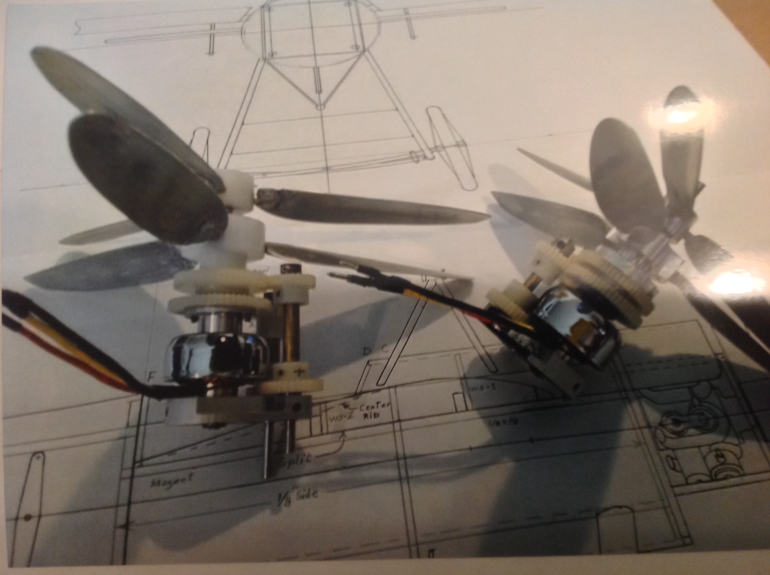
Photos of various motors
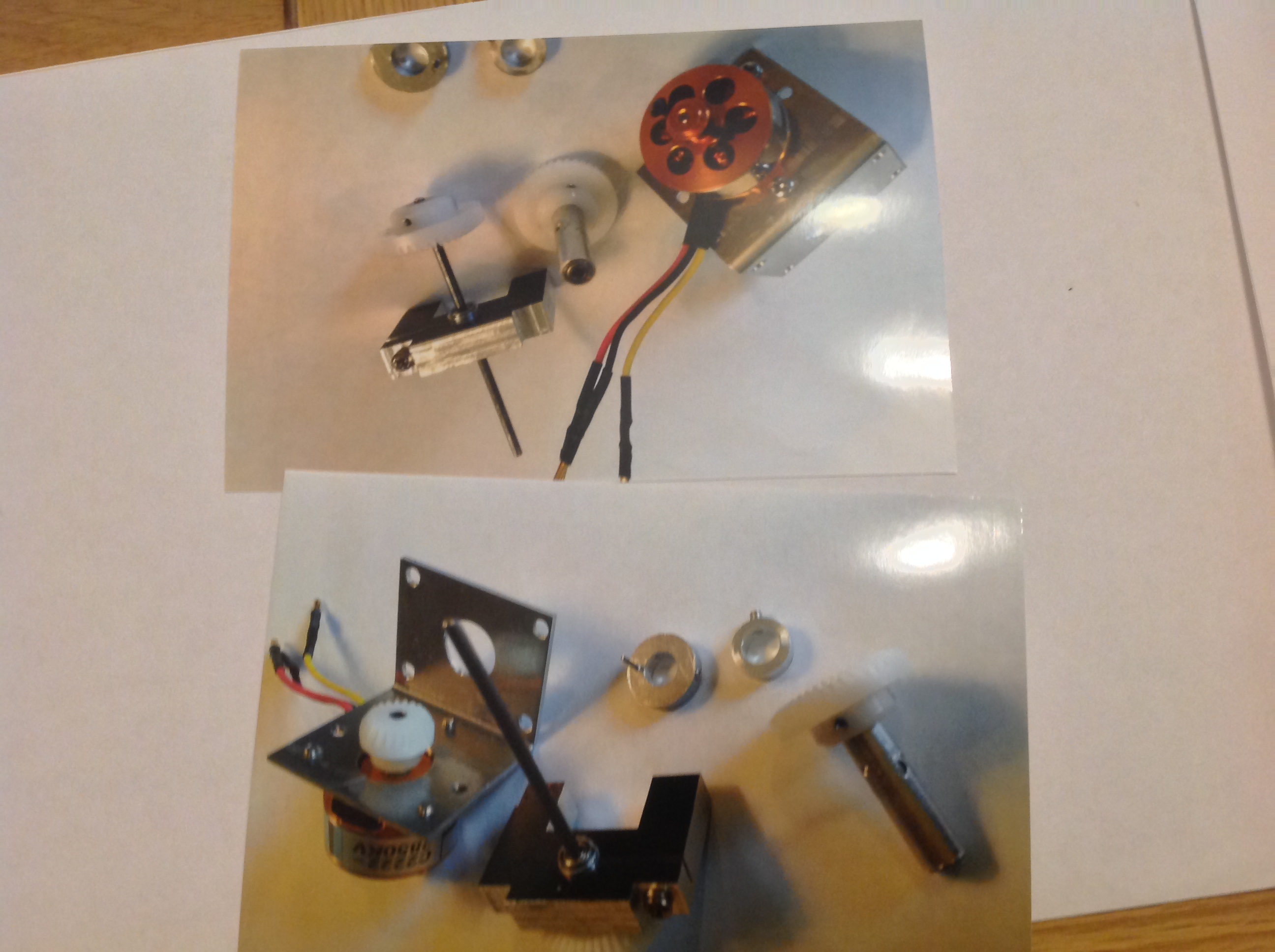
Using drawing concept 10. First start by making bracket ‘D’ and fitting the motor according to the drawing, bracket ‘E’ is also made and fitted, the main support for the motor and propeller shaft, this is followed by cutting the 2mm music wire to a length of 80mm, the next step is preparing the metric gears, you start with the 20 tooth gear item ‘B’ which is fitted to the motor, first you insert a 3mm O/D aluminium tubing into the gear this is extended about 1/2 mm beyond the shaft end this prevents the gear from rubbing on the motor body, this tubing is glued in place with C.A super glue, drill 3 holes 120 degrees apart in the shank of the gear wheel, these are tapped for 2.56 screws or equivalent, the gear can now be fitted to the motor and secured by the 3 small screws using MIP hex tool.

The 40 tooth gear item ‘A’ is now attached to the main 2mm drive shaft for the front propeller, this gear wheel comes with a 4mm hole which requires bushing down to 2mm by using 4 and then 3 mm tube these are now glued in place using C.A. again 3 holes are drilled in the shank as above for fixing screws, gear wheel ‘C’ is now drilled out using a 6mm drill and again drilled and taped for 3 screws, care must be taken not to over tighten these screws as they can strip their threads very easily, aluminium gears would be better if a suitable supplier could be found.
Tubing assemblies. First of all I must point out that all bearings and shaft fits must be as tight as possible to prevent excessive side and vertical propeller shaft movement, item ‘F’ is the main shaft support held in place by bracket ‘E’ with the screw shown, this has bearing at each end for the 2mm shaft it also has a spacer between the 2 bearings, gear wheel ‘A’ with its shaft and item ‘F’ are now assembled, item ‘G’ and gear wheel ‘C’ are fitted onto the 2mm shaft and secured with the 3 screws in the gear wheel, so you now get the idea as gear wheel ‘B’ turns ‘A’ turns in one direction and ‘C’ turns in the other, finally all that is left to do is to add the two propeller fixing collars ‘H’ and ‘I’ both have the same small screw fixing as already used on the gear wheels, the rear collar also has a small pin fitted that locates into the rear of the propeller to stop it from spinning on the shaft these collars can be adjusted to suit the propeller width, fit the propeller nut on the front and you are nearly ready to go, check all clearances and that the motor and gears turn over smoothly, add a few drops of silicon to lubricate the gears and happy flying.

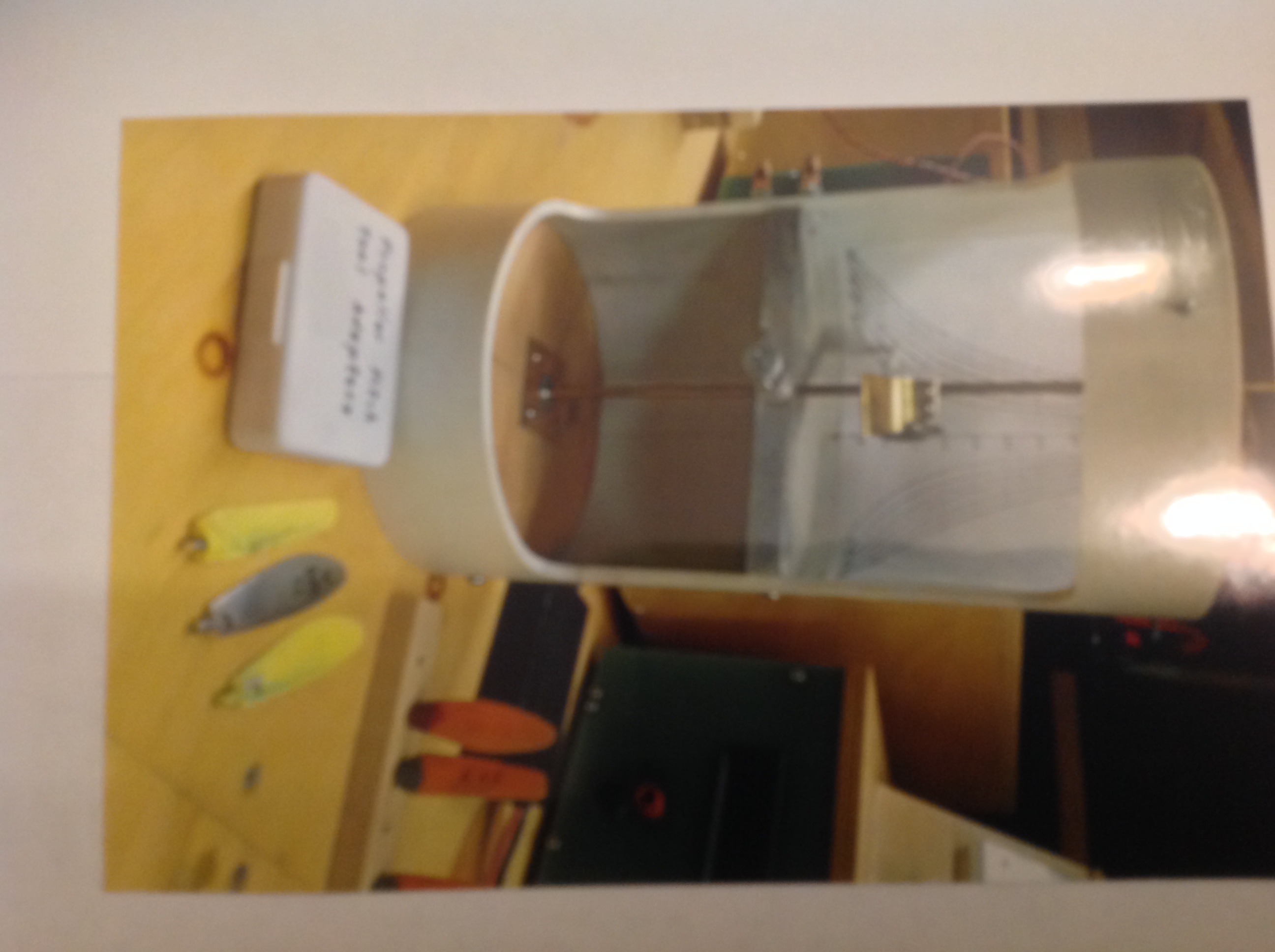
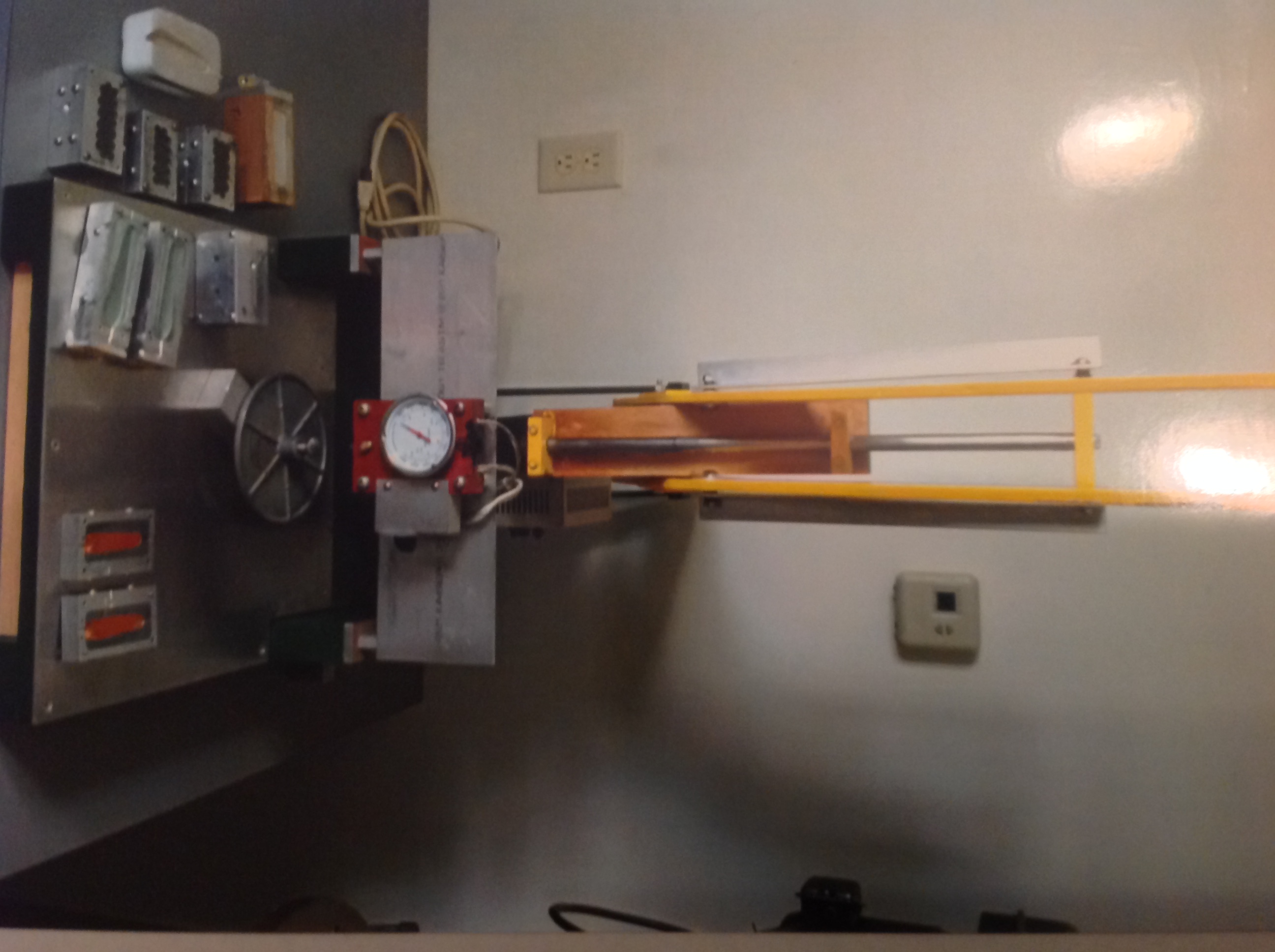
Test Equipment. With all this design and research you need a comprehensive system for running and recording all data from testing. Mert has two set-ups the main one in his workshop and a second one on a movable trolley which is used in the office, the main rig comprises of two power supplies one rated at 100 Amps 2 cell and the other 50 Amps at 3 Cell voltage, the hinged test stand can measure forward thrust in ounces and side torque from each propeller, air blowers are calibrated to provide headwind, a tachometer on top of the large power supply will read speed from one blade up to 6 blade propellers, the whole rig took 3 months to design, the portable test rig is similar and works the same apart from no torque readings and a single tachometer reading, this is mainly used for 2 cell batteries adjustable from 5 VDC to 8 VDC.
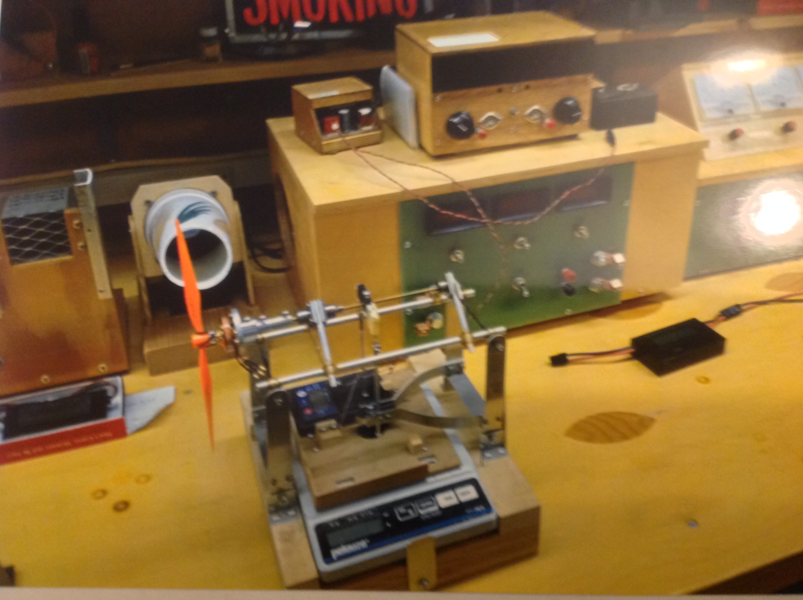

Two test rigs
I must congratulate Mert on his dedication and drive over this period of about 19 years to research, design and manufacture all these different parts bearing in mind non of this material and information on how to do it was available on the public domain, I think many people would have given up “you are the man” Mert has also produced a comprehensive list for all proposed aircraft designs fitted with contra rotating propellers, many were not built however the list covers 28 pages.
